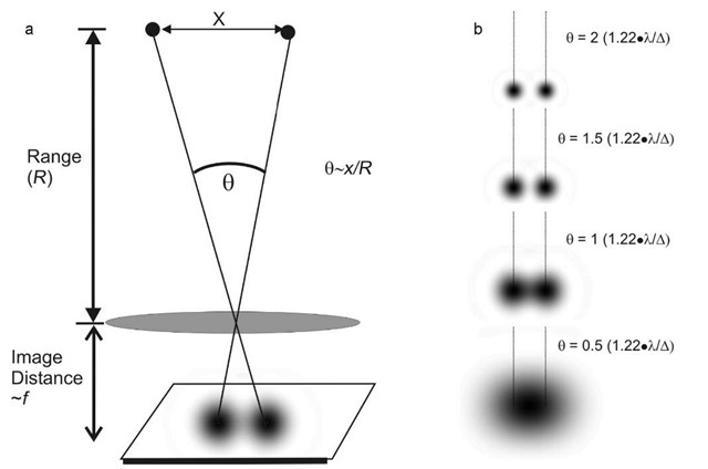

It consists of a bright central circle, the Airy disc, which contains 84% of the total light intensity, with the remaining 16% distributed across a series of progressively less intense concentric rings. For a perfect imaging system with no aberrations, this pattern is also known as the Airy pattern and is shown in Figure 1.

The diffraction pattern of a point emitter in the image plane of a microscope is described by the 2D point spread function (PSF). When a point emitter (such as a quantum dot) is imaged by a microscope, its image is blurred due to diffraction. This is shown clearly in both animated images and real-world examples of fluorescence microscopy images.The lateral (X-Y) resolution of fluorescence and Raman microscopes is frequently calculated using the famous Rayleigh Criterion for resolution, 0.61 λ/NA, but where does this resolution limit arise from and how does it relate to the other resolution limits encountered in microscopy? For this reason, objects in a diffraction limited image of a sample will never appear smaller than the PSF.

The analogy she uses is of the PSF being like a paint brush of a particular size, used to create an optical image from all the point sources in an image. She likens the process of convolving each point source in the sample with the PSF as “stamping a PSF on every point-source in the sample”. Waters also helps viewers connect the PSF to real-world insights: for example, (citing Vogel et al, Science, 2006) one can fit ~3million GFP molecules into the PSF maxima of a typical high NA objective! This video is also very helpful in integrating in the viewer’s mind the concept of the PSF with the well-known Rayleigh Criterion.

She further explains that the PSF is a result of diffraction and interference: this concept is concretized in the video with the help of animations and examples. Jennifer Waters defines the PSF of a microscope and then shows how it relates to the resolution of a microscope. The Point Spread Function (PSF) of microscope is the basis for many practical and theoretical concepts in light microscopy, both basic and advanced. Imager Diagonal is larger than the Field Number of the Objective. Actual values mayĥ) Vignetting, a darkening of the image at the corners, may be observed if the (WD) and Field Number (FN) are shown for reference only. Maximum pixel size = R*magnification/2ģ) Camera and Objective combinations which meet the Nyquist criteria and are therefore diffraction limited are indicated by showing the Limiting Resolution in green font. R = 1.22*λ/(2NA)Įstimated by applying the Nyquist criteria to the minimum feature size as itĪppears on the imager plane. Minimum feature size is estimated using the Rayleigh Criteria at λ = 550nm it can be re-calculated for other wavelengths. Please contact our imaging experts for assistance in selecting a camera & objective combination that fulfils your FOV & resolution requirements at application-specific wavelengths. This table also applies to cooled sCMOS cameras such as the pco.edge 4.2, pco.edge 4.2bi and pco.edge 4.2bi uv cameras.Įstimated Performance of Camera and Objective Combinations In the table below, we show the Limiting Resolution (in µm) and the Field of View for several commercially available microscope objectives when used with a 2048 x 2048 camera with 6.5µm pixels: this includes non-cooled sCMOS cameras such as the pco.panda 4.2, pco.panda 4.2bi and the pco.panda 4.2bi uv. The above method can be used to estimate the performance of a camera and a microscope system, as long as the relevant parameters of the camera and the microscope objective are known. Using the Numerical Aperture of a microscope objective to estimate the Nyquist-limited maximum pixel size In the following table, “R” represents the Rayleigh Criterion for the diffraction-limited spot size: R = 1.22λ/(2NA) Objective This can be quantified by applying the Nyquist Criterion to the spatial sampling on the image plane, leading to an upper limit on the pixel size of the image sensor that is used in conjunction with a microscope. Lichtman then shows a sequence of images taken with cameras that have different pixel pitches providing a visual insight into why the sampling in the image plane must be sufficient to resolve an image. Our main takeaway is that the higher the NA, the smaller the Rayleigh Criterion and the better the resolution. We learn about the Rayleigh Criterion, and that it is different for the XY and XZ planes of a microscope. How close could two points be in the sample plane and still be resolved as separate points in the image. Lichtman leverages the previously explained concepts of diffraction, NA and PSF and builds up to the final payoff: optical resolution.


 0 kommentar(er)
